









Event Radio Coverage Problems: Interference & Repeater Checks
Use records and measurements to investigate interference and reliable coverage in both directions.
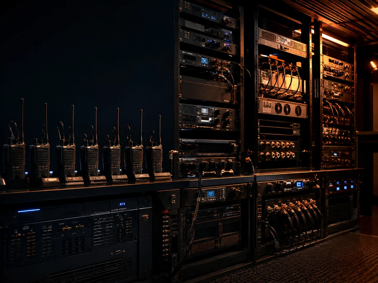
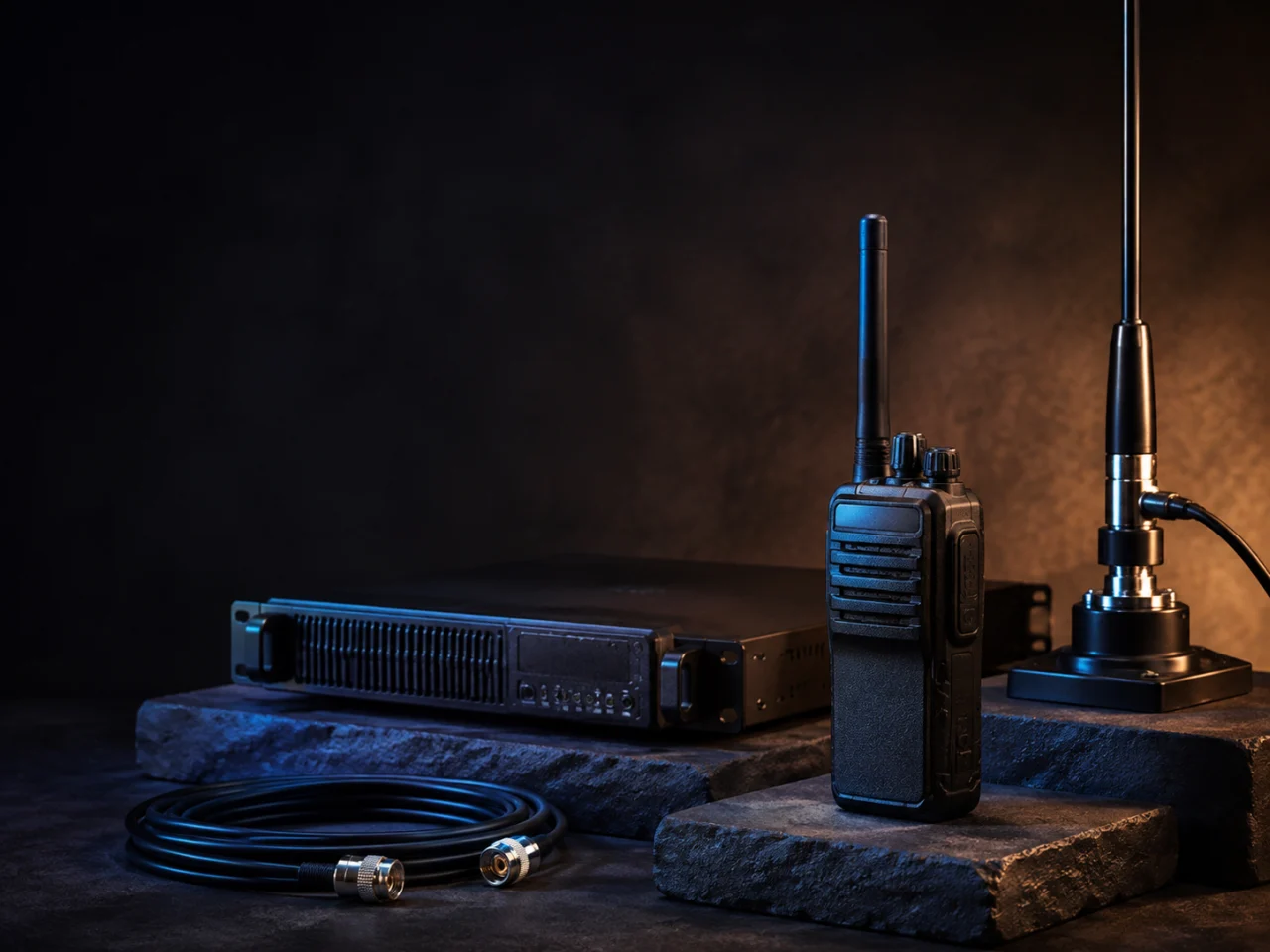
AI-generated illustration · Not an event photographWhen radios produce noise, broken audio or fail to reach distant users, investigate both the radio environment and the complete transmit/receive chain.
Major events bring multiple teams and systems into a limited area. Frequency coordination, receiver performance and site deployment therefore matter more. ITU recommends stronger spectrum monitoring and close coordination with frequency-assignment personnel for such events.Source: ITU National Spectrum Management Handbook, §4.5.5
Assess actual transmissions, configurations and measurements. Registration or coordination does not itself generate RF interference. The number of channel records cannot directly determine the usable range of every device.
Distinguish four interference mechanisms
Similar symptoms, different mechanisms
Select a mechanism to explore the concept. Confirm the actual cause through configuration checks and measurements.
Signals overlapping at the receiver may mask speech or affect decoding.
Adjacent-channel effects depend on frequency spacing, signal strength and equipment performance.
A nearby strong signal may weaken reception of a wanted weak signal, even on a different channel.
Nonlinear stages may create a new interference component that falls within the receive channel.
Co-channel interference: different signals use the same frequency and overlap at the receiver, potentially masking speech or preventing correct decoding.
Adjacent-channel interference: a signal on a neighbouring channel affects reception. Its impact depends on relative signal levels, frequency spacing, transmitter characteristics and receiver selectivity.
Receiver blocking or desensitisation: a nearby strong signal may reduce the receiver’s ability to receive a weak signal, even when the systems use different channels.
Intermodulation interference: multiple signals passing through a nonlinear stage may create interference components within the receive channel.
ETSI tests co-channel, adjacent-channel, intermodulation and blocking performance separately. They require different investigations. A busy radio environment alone does not identify the particular cause.Source: ETSI EN 300 086, §§8.3, 8.4, 8.6, 8.7
Shorter range may mean less reliable coverage
When interference increases or receiver performance falls, positions near the coverage edge may first experience broken audio, noise or lost communication. Obstructions, terrain, antenna position, feeder losses, equipment condition and configuration can also affect coverage.
Ask which positions, directions, times and configurations cannot support reliable communication. Manufacturers also explain that actual range depends on terrain, obstructions and electromagnetic interference.Source: Motorola Solutions range conditions
Check whether the repeater can hear the handheld
Hearing the call is only half the link
Select a direction to explore the path. The animation illustrates signal flow, not measured performance or guaranteed coverage.
Verify each direction separately at critical positions.
Illustration · Not site measurement data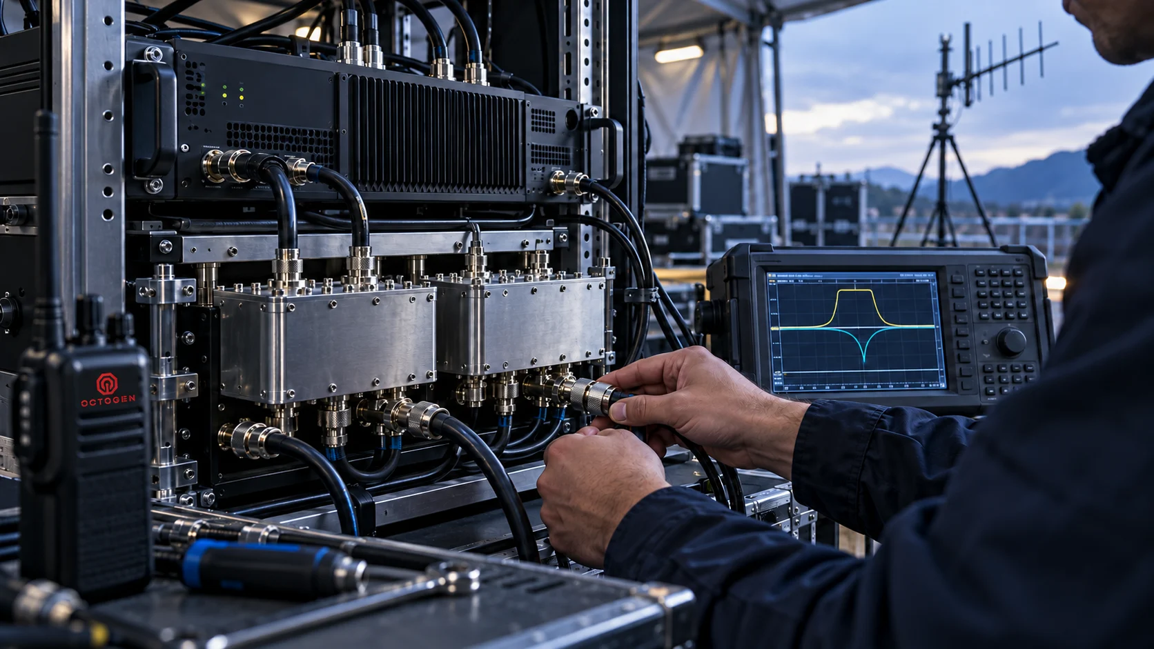
A repeater system has a handheld-to-repeater uplink and a repeater-to-handheld downlink. Hearing the repeater at a position does not prove that the repeater can reliably receive transmissions from that handheld.
For a duplex repeater transmitting and receiving simultaneously, also check the duplexer, filtering and antenna isolation. Excessive transmit energy entering the receive chain can reduce reception while the repeater transmits. ETSI specifies a separate receiver-desensitisation test for duplex operation.Source: ETSI EN 300 086, §9.1
Compare performance when equipment is idle and when it is transmitting. Check antennas, connectors, feeders, filters and installation locations rather than relying on a single call beside the equipment cabinet.
Keep four records in the communications plan
1 Traceable configuration and coordination records
Specify radio models, operating areas, frequencies, bandwidth, power, mode and applicable assignment conditions. Record the organiser’s communications lead. Check certification separately from frequency-use arrangements, and assign responsibility for on-site changes.Source: SIRIM certification information, MCMC Spectrum Plan, Chapter 3
2 Measurements aligned with event operation
Record the radio environment before and after deployment and activation of major transmitting systems. Plan retests according to risk. A single scan with no detected signal does not establish that a frequency will remain available throughout the event.
3 Two-way coverage acceptance at critical positions
Test speech and call success along actual working areas and staff routes. Where appropriate, record signal strength, analogue audio quality or digital bit-error metrics. Agree acceptance thresholds in advance; signal bars alone do not establish a pass.
4 Peak-time operation and incident procedures
Confirm simultaneous-call requirements, channel capacity, backup power, backup contact methods and who records, coordinates and handles interference. Radio planning must consider propagation, interference, traffic load and local frequency restrictions together.Source: ETSI DMR General System Design, §10.2.3
Choose changes for the confirmed cause
Tone squelch or selective calling helps filter the calls a user hears, but does not create additional radio-frequency resources. Digital operation still needs interference and coverage assessment. Higher transmit power does not remove obstructions, repair a receive chain or replace frequency coordination.Source: Icom selective-calling features, ETSI DMR system design
Choose measures based on measurements, within lawful authorisation and on-site coordination. Options may include antenna-position changes, better isolation and filtering, adjustments to an approved channel plan or a different coverage arrangement for working areas.
Planning a major event, or investigating recurring communication dead zones? Give Obor the venue plan, existing equipment, principal staff routes and issue records so the scope of a site survey, frequency-coordination support and system acceptance can be assessed.