


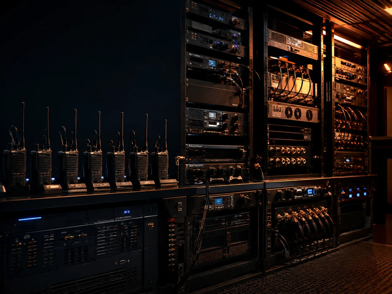
SECTION 01 / SIGNAL ROOMSIX GUIDES.
SIX GUIDES.
ONE EQUIPMENT ROOM.
Explore the repeater, six-way charger, DC backup, BDA / DAS head-end, RF distribution and alarm monitoring system.
EXPLORE THE GUIDES →Trace a radio repeater DC backup path from mains input to rectifier, battery, protected DC bus and alarm—and learn what runtime figures leave out.
FIELD DECISIONSpecify the load and required operating time first. Battery size is an outcome of that calculation, not the starting point.
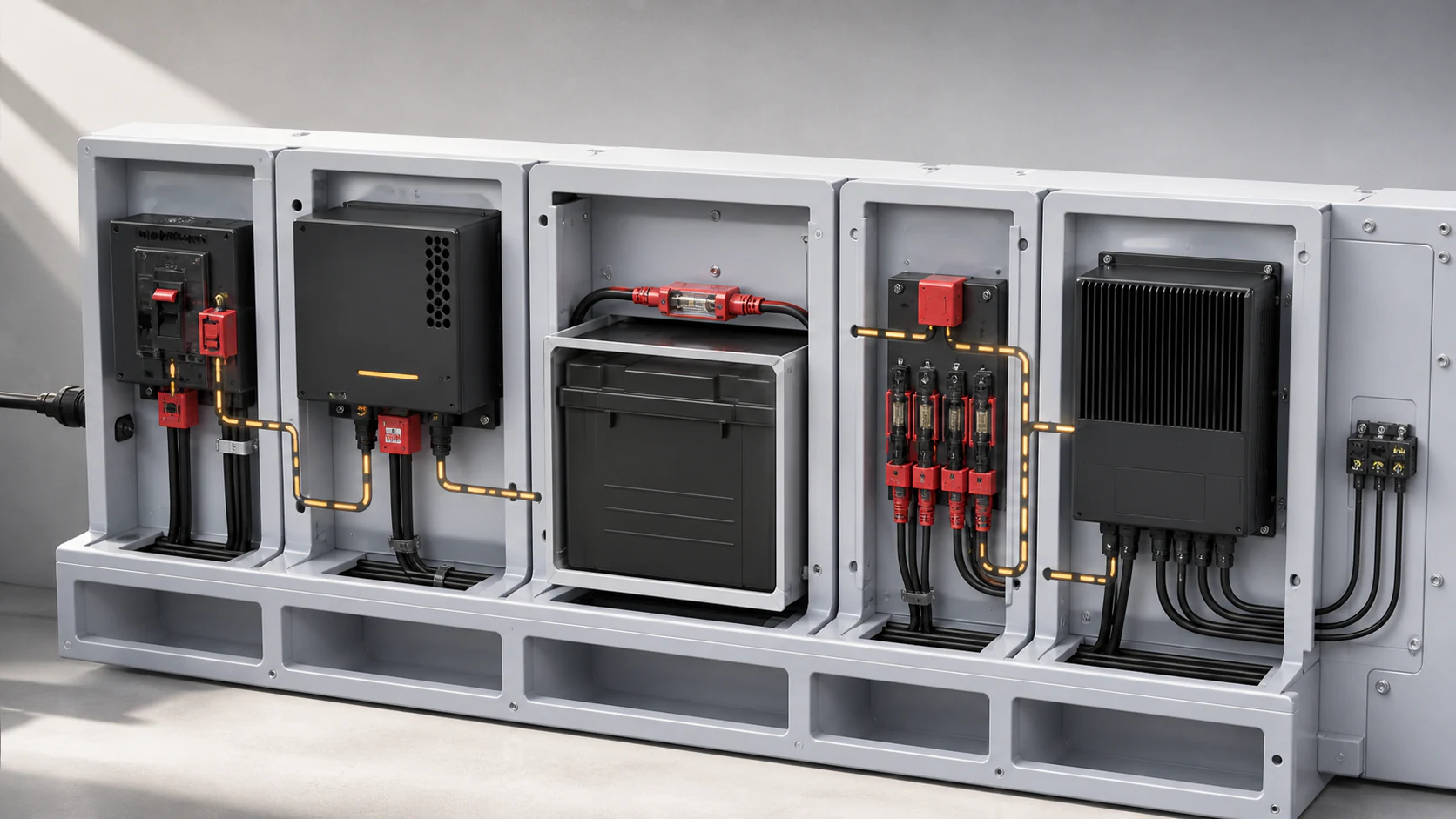
A repeater DC backup system normally uses a rectifier or charger to supply the DC load and maintain a battery reserve while mains power is healthy. When mains fails, the protected battery path supports the repeater and selected network equipment. Runtime depends on usable battery capacity, DC load, battery age, temperature, cabling and the permitted discharge limit.
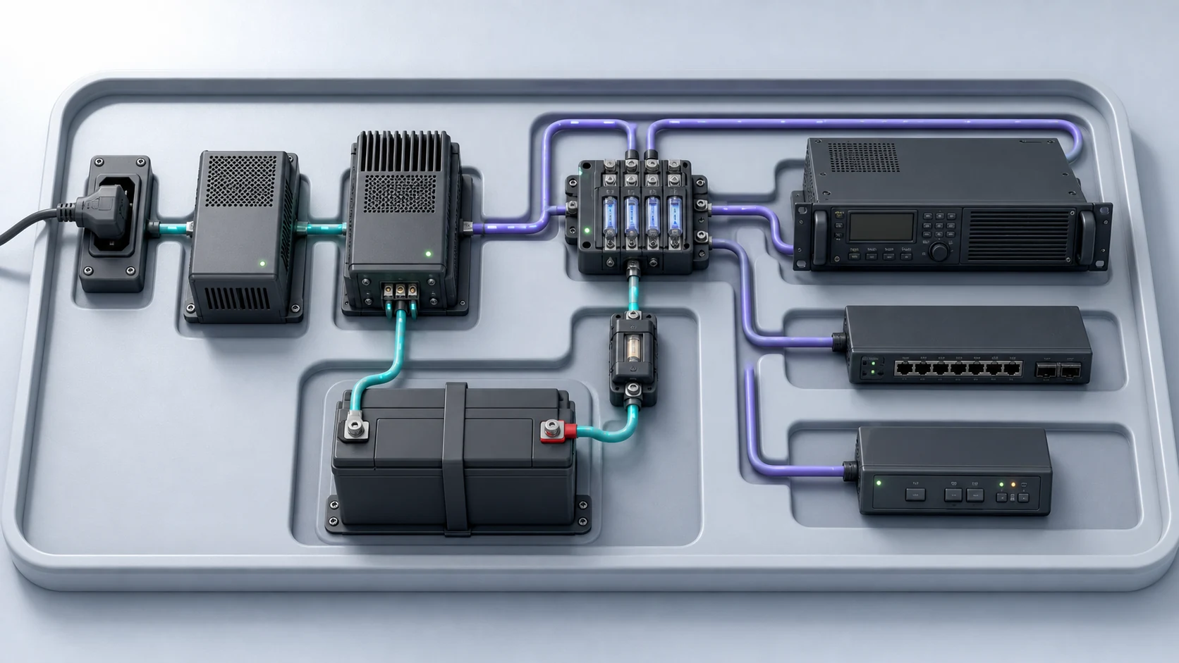
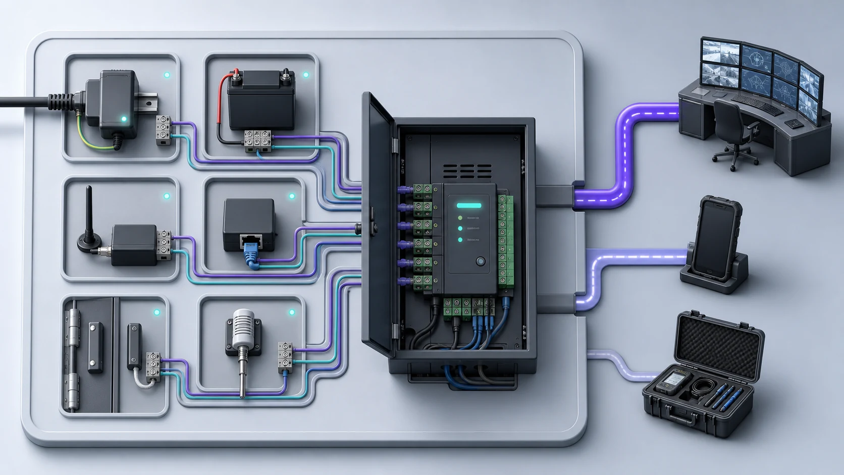
Concept illustration of AC input, a rectifier/charger, battery reserve, a fused DC bus, and radio, network and alarm loads. Actual wiring, capacity and isolation must follow the selected equipment and the manufacturer’s system design guidance.
A protected mains circuit supplies the rectifier and charger.
The power module feeds the DC bus and maintains the battery.
A fused battery bank holds the reserve energy.
The DC path remains continuous when AC disappears.
Low voltage, battery and AC-fail contacts reach the monitoring point.
List every protected load, including network switches, links and cooling controls that the radio path needs.
Measure steady and peak DC current instead of relying only on nameplate estimates.
Set fusing, cable size, disconnects and enclosure ventilation for the chosen battery system.
Test the complete AC-fail sequence and record voltage, alarms and recovery behaviour.
The RF path can still fail if a router, remote unit or alarm interface loses power.
Age, temperature, discharge limits and wiring loss reduce usable reserve.
A charger showing normal does not prove the battery path will carry the actual load.
There is no universal runtime. It must be calculated and then tested from usable battery capacity, total DC load, battery condition, temperature, discharge limit and conversion loss.
Yes, when that equipment is required for the end-to-end radio service. Define the protected load list before sizing the battery system.
Common points include AC fail, charger fault, battery low, battery disconnected and low DC bus. The final list depends on the equipment and response plan.
Repeater battery-charger and alarm interface example.
AC and battery alarm behaviour.
Product references illustrate operating principles and available equipment features. Final design, compatibility and regulatory decisions must follow the selected equipment, site survey and applicable Malaysian assignment conditions.
Obor Kuasa can survey the site, engineer the system and document the commissioning results around the way your team actually works.
REQUEST A SITE AUDIT






 SR / 01
 SR / 02
 SR / 04
 SR / 05
 SR / 06