


SECTION 01 / SIGNAL ROOMSIX GUIDES.
SIX GUIDES.
ONE EQUIPMENT ROOM.
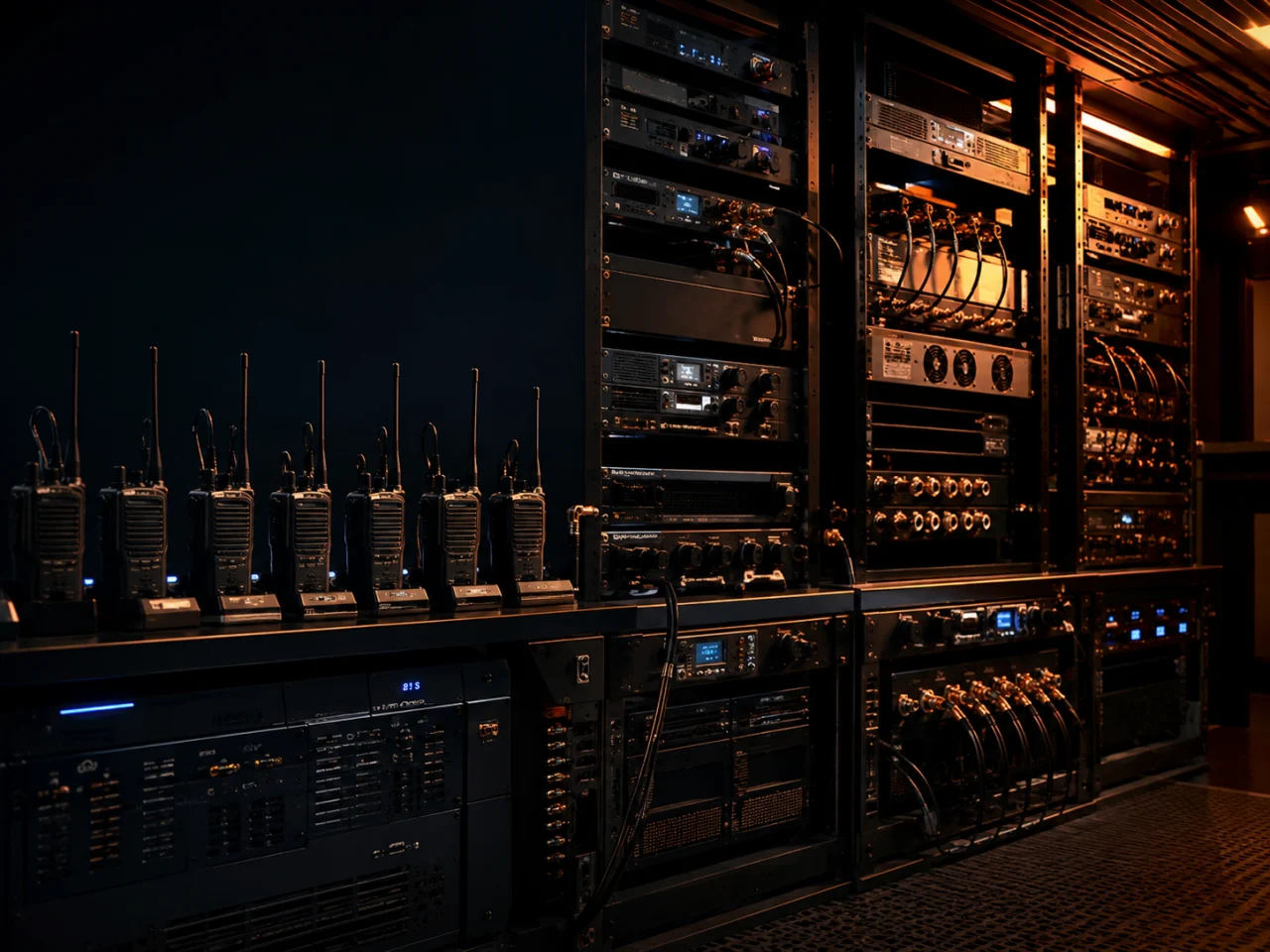
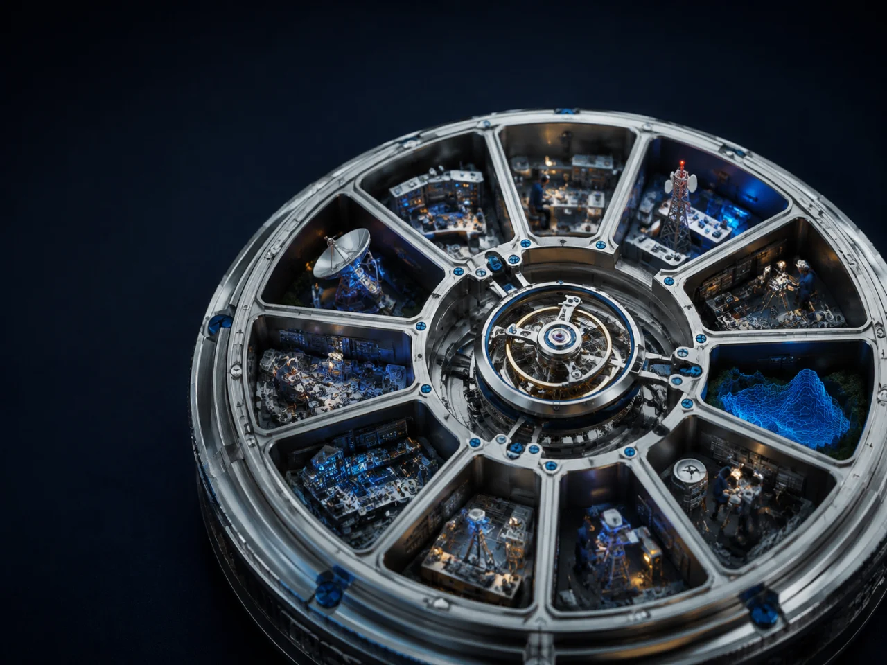
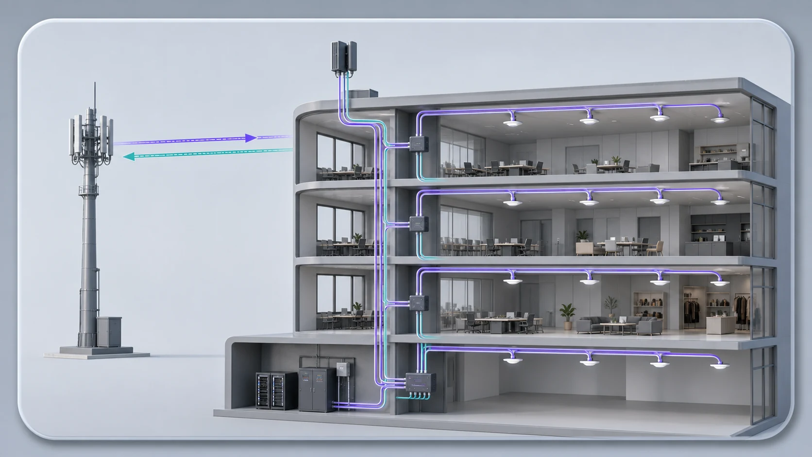
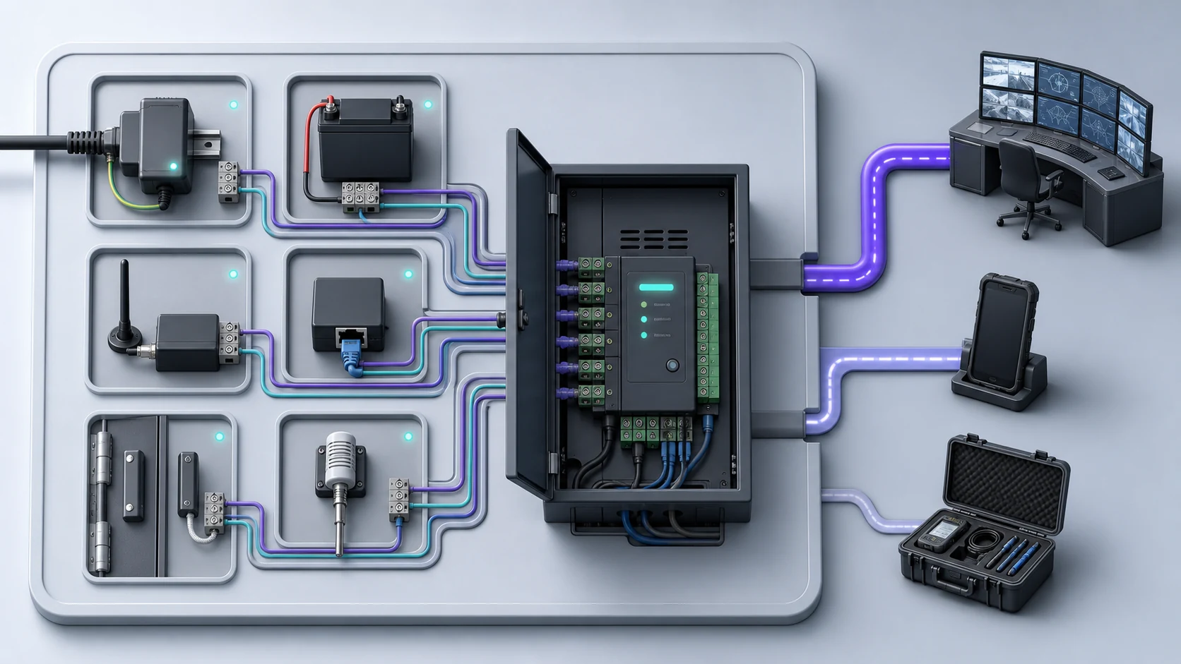
Explore the repeater, six-way charger, DC backup, BDA / DAS head-end, RF distribution and alarm monitoring system.
EXPLORE THE GUIDES →Follow one conditioned RF feed through filters, splitters, couplers, protection and feeder outputs—and see what technicians need at handover.
FIELD DECISIONDesign each branch from its target antenna level and measured loss. A tidy panel is useful; a documented link budget is what makes it serviceable.
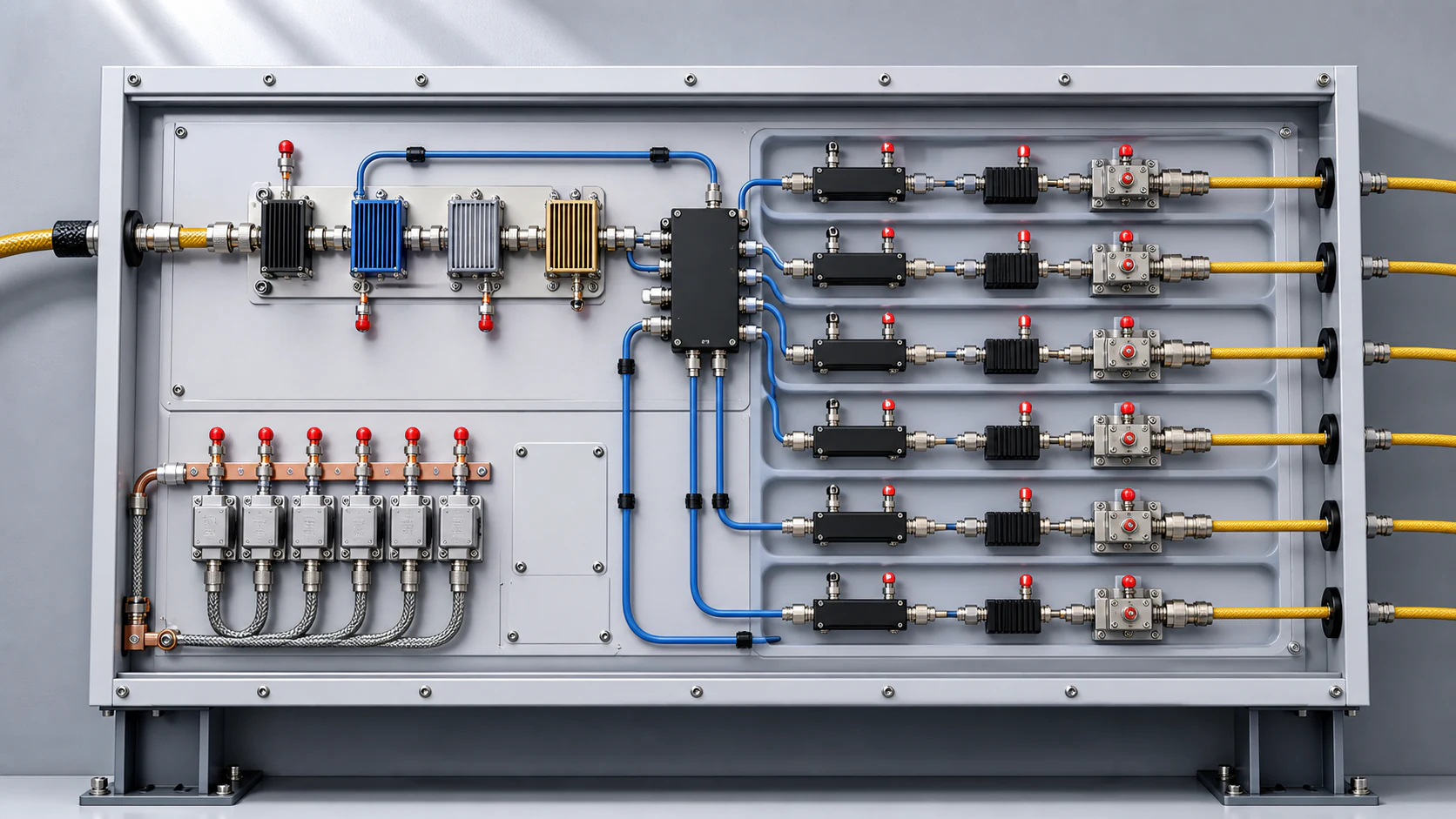
An RF distribution panel turns one or more conditioned radio feeds into controlled branches for different building zones. Filters select the wanted band, splitters divide power, couplers set unequal branch levels or provide test samples, attenuators trim a path, and surge protection helps manage energy entering from exposed feeder routes.
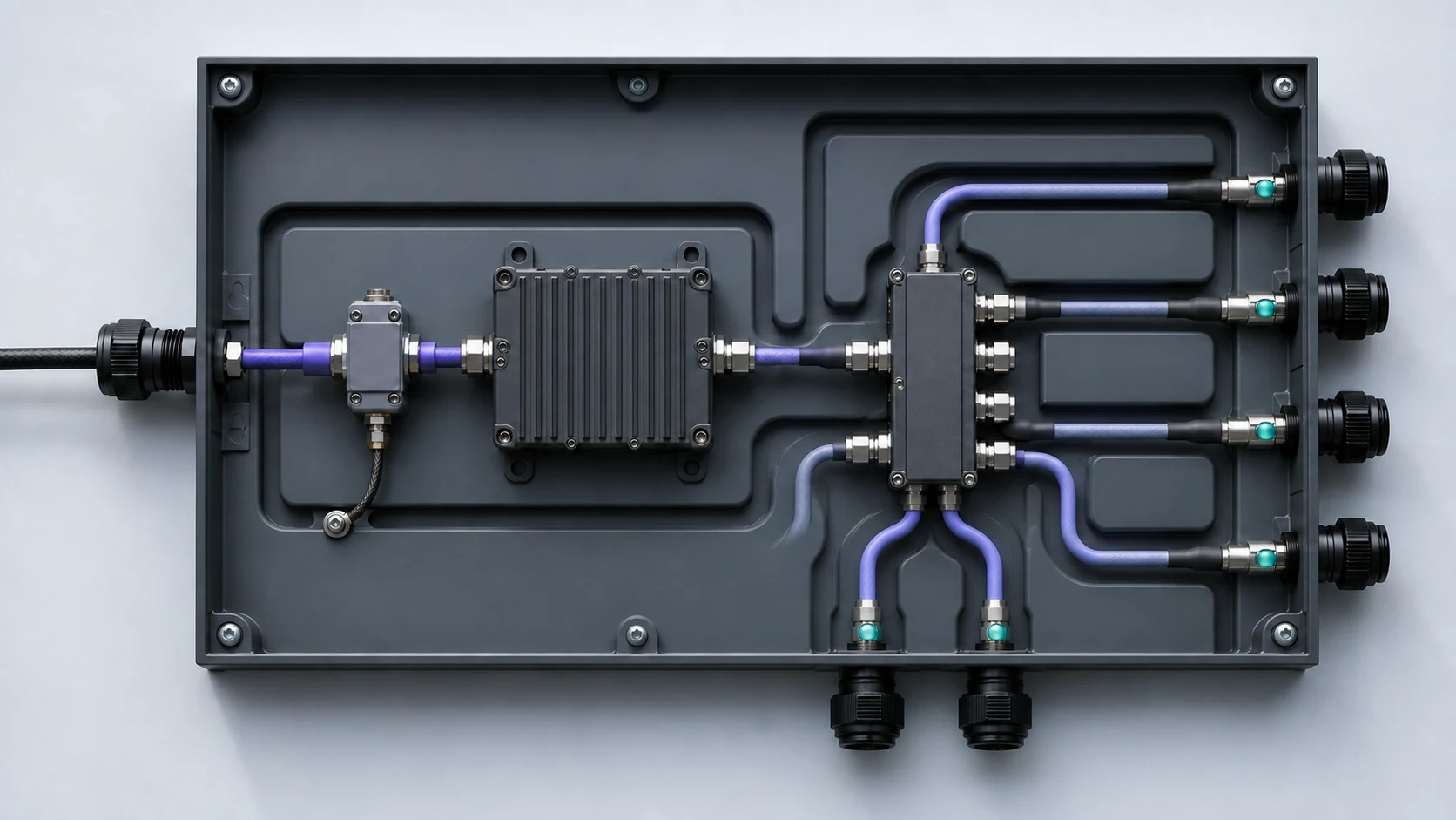
A traceable panel controls the common RF path and separates it into six serviceable feeder branches.
Band filtering keeps the intended RF path separated from unwanted energy.
A splitter creates equal branches when the downstream losses are similar.
Directional couplers feed unequal routes without wasting power in heavy attenuation.
Bonding and surge devices support the site protection design.
Labelled feeder outputs continue to the planned antenna zones.
Record the expected input level, passive loss and target output for every feeder branch.
Keep bend radius, connector torque, cable support and low-smoke material requirements in the installation method.
Provide accessible test points without forcing technicians to disturb a live branch.
Measure return loss or VSWR and branch levels after the final antenna and feeder work is complete.
Two branches with different feeder lengths and passive losses will not deliver the same antenna level automatically.
A loose, contaminated or badly prepared connector can add loss, reflections and intermittent faults.
Without cable IDs, device values and measured levels, later fault finding becomes guesswork.
A splitter divides input power across outputs, commonly in equal ratios. A directional coupler samples or diverts a defined portion of the signal, which helps balance branches with different losses.
They let a technician check level and signal condition without disconnecting a main feeder. The test-point coupling value must be known when interpreting the measurement.
Include the schematic, device values, feeder IDs, connector and cable details, branch calculations, measured input/output levels, return-loss results and clear panel photographs.
Official examples of splitters, couplers, tappers and radiating feeder systems.
Passive and active in-building distribution context.
Product references illustrate operating principles and available equipment features. Final design, compatibility and regulatory decisions must follow the selected equipment, site survey and applicable Malaysian assignment conditions.
Obor Kuasa can survey the site, engineer the system and document the commissioning results around the way your team actually works.
REQUEST A SITE AUDIT





 SR / 01
 SR / 02
 SR / 03
 SR / 04
 SR / 06